


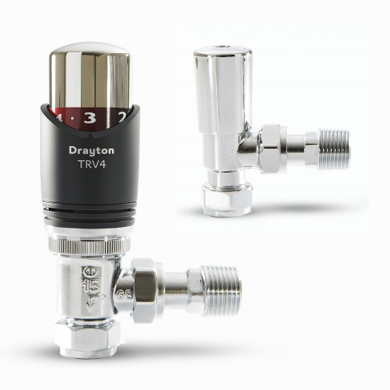
What Is a Thermostatic Radiator Valve (TRV)?
A thermostatic radiator valve (TRV) is a valve that is fitted to a radiator in order to control the flow of hot water through the radiator. This allows you to control the temperature of the room in which the radiator is located.
How does a TRV work?
TRVs work by sensing the air temperature around them. When the air temperature reaches the desired level, the TRV will automatically close down the flow of hot water to the radiator. This will help to prevent the room from overheating.
How to set a TRV
TRVs are typically numbered from 0 to 5, with each number corresponding to a different temperature range. The higher the number, the warmer the room will be.
- 0: Frost protection
- 1: 10°C
- 2: 15°C
- 3: 20°C
- 4: 25°C
- 5: 30°C
Once you have set the desired temperature for the room, you should leave the TRV alone. Turning the TRV up to a higher setting will not make the room heat up any faster. It will simply use more energy.
Where to place a TRV
TRVs need a free flow of air to sense the temperature, so they must not be covered by curtains or blocked by furniture.
How to use a TRV in conjunction with a room thermostat
A room thermostat is used to control the overall temperature of your home. It works by sending a signal to your boiler, which tells the boiler when to turn on and off.
If you have a room thermostat, you should not normally need to use a TRV in the room with the thermostat. This is because the room thermostat will already be controlling the temperature of that room. However, if you do have a TRV in the room with the thermostat, you should keep the TRV on the maximum setting and adjust the room thermostat as explained in the instructions.
Benefits of using TRVs
Using TRVs can help you to save energy and money. This is because they will only allow the radiators to heat up to the desired temperature, which will prevent you from wasting energy.
In addition, TRVs can help to improve your comfort levels by providing you with more control over the temperature of each room in your home.
Conclusion
For more information on the thermostatic radiator valves (TRV) that we stock, please visit here.